Basics: Orifices for flow measurement
Orifice plates are usually differentiated by their type of installation, type of differential pressure tapping and the shape of the orifice.
The characteristic differential pressure is created by the orifice bore which is the defined circular opening. It is usually of square edged concentric type according to ISO 5167-2 positioned in the middle of the pipe.

The main features are a sharp edge, a cylindrical bore of a certain length and a conical bevel tapering to the rear. Alternatively, the relevant standards provide for deviating designs, which are used for applications with highly viscous (e.g. quarter-circle nozzles) or contaminated media (e.g. segment orifices).
The standard design is permitted by the standard for an inner diameter of the pipe between 50 mm and 1000 mm. For pipes with smaller inside diameters, standards such as ISO 15377-TR or ASME MFC-14M which go beyond these standards must be taken into account. Orifice plates for pipes with small inside diameters are usually designed as meter tubes.
In order to reduce the uncertainties of these meter tubes, the devices can be calibrated on a flow test bench if required on request.
Types of differential pressure tappings
The differential pressure can be tapped in different ways:
Corner tapping
Directly in front of and behind the orifice plate an opening is placed in the corner of a carrier ring to measure upstream and downstream pressure. Both pressure signals are routed through these openings to the outside.
Corner tapping with annular chamber
The orifice plated is held by an annular chamber. Upstream and downstream pressure are measured through an annular gap opening between carrier ring and orifice plate. Both pressure signals are averaged over the entire circumference and routed outside.
Flange tapping
The orifice plate is held between two so-called orifice flanges. Upstream and downstream pressure signals are measured through flange taps which are drilled into the flanges.
Tapping with distance D, D/2
The orifice plate is held between regular flanges. Upstream and downstream pressure signals are measured through taps in the pipe with distance of D (upstream) and D/2 (downstream) to the orifice plate.
Designs
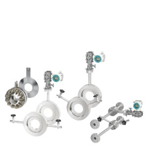
- Orifice plate with pressure tappings (7ME171)
- Orifice plate with annular chamber (7ME172)
- Orifice meter run (7ME173)
- Orifice plate (7ME174)
- Orifice plate with orifice flange (7ME175)
Mounting arrangements
For more information on installation position and piping, please see the Operating Instructions "SITRANS FPS200" on SIOS.
The orifice plate is installed between two flanges in the pipeline. Using condensation pots (for steam) and initial shut-off valves, the differential pressure of the high-pressure side and low-pressure side is directed through differential pressure lines to a manifold and to the differential pressure transmitter. For fluids with pressure and temperature fluctuations it makes sense to take an additional measurement of the pressure and temperature in order to correct the flow signal of the transmitter in a subsequent correction computer.
Selection of mounting point
The flow measuring regulations DIN EN ISO 5167 not only consider the design of primary differential pressure devices, but also assume that their installation is in accordance with the standard so that the specified tolerances can be retained. The required inlet and outlet pipe sections according to ISO 5167 can be found in the calculation protocol of the respective orifice plate. Configuration of the pipeline should allow for standardized installation (required inlet and outlet pipe section). Particular attention must be paid to ensure that the primary device can be fitted in a sufficiently long straight section of pipe. Bends, valves and similar should be fitted sufficiently far upstream of the primary device to prevent them having a detrimental effect. Primary devices with a large diameter ratio are particularly sensitive to interferences.
Design of measuring point
The design of the measuring point depends on the medium and on the spatial conditions. The designs for gas and water only differ with regard to the position of the tapping sockets (see section "Tapping sockets"); condensation pots are provided for steam applications.
Orifice meter runs
On lines with small nominal diameters (DN 10 to DN 50) the measurements are influenced by the wall roughness and diameter tolerances of the pipes, more than measurements with larger nominal diameters. These influences are counteracted by using orifice meter runs with fitted inlet and outlet pipe sections made of precision pipes. For exact measurements with orifice meter runs, the flow coefficient C can be determined by means of calibration.
Z-Options for cable glands, plugs, labeling, approvals, blanking plugs, flanges seals, device settings, etc. according to SITRANS P320


 Giỏ hàng
  Danh mục sản phẩm