NHÀ PHÂN PHỐI CHÍNH THỨC CỦA HÃNG SIEMENS VÀ HACH TẠI VIỆT NAM

Danh mục sản phẩm

Đặt hàng nhanh

Danh mục sản phẩm

SITRANS FVA250 Overview

Đánh giá trung bình

(5/5)

1 Đánh giá

  • Mã sản phẩm:

    Thương hiệu: Siemens

  • Danh mục:

    SITRANS FVA250

  • Tình trạng:

    Còn hàng
  • Giá:Liên hệ

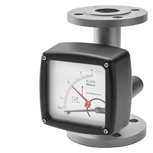
SITRANS FVA250 là một bộ cảm biến dòng chảy đo khí hoặc chất lỏng của Siemens. Bộ cảm biến này sử dụng công nghệ siêu âm để đo lượng chảy một cách chính xác và đáng tin cậy trong các ứng dụng công nghiệp và quy trình.

Dưới đây là một số điểm nổi bật về SITRANS FVA250 của Siemens:

  1. Công nghệ siêu âm: SITRANS FVA250 sử dụng công nghệ siêu âm để đo lượng chảy của khí hoặc chất lỏng trong các đường ống hoặc ống chảy.

  2. Đo lượng chảy đa pha: Bộ cảm biến này có khả năng đo lượng chảy của các chất lỏng có chất rắn hoặc hạt lơ lửng, hoặc đo lượng chảy của các loại khí khác nhau.

  3. Độ chính xác và đáng tin cậy: SITRANS FVA250 cung cấp độ chính xác cao và đáng tin cậy trong việc đo lường lưu lượng, giúp người dùng đảm bảo hiệu suất ổn định và hiệu quả của các quy trình công nghiệp.

  4. Đa dạng ứng dụng: SITRANS FVA250 có thể được áp dụng trong nhiều lĩnh vực công nghiệp như hóa chất, dầu khí, thực phẩm và đồ uống, và các ứng dụng quy trình khác.

  5. Dễ dàng lắp đặt và sử dụng: Thiết kế kẹp chặt không xâm nhập vào chất lỏng hoặc khí, giúp dễ dàng lắp đặt và bảo trì, không yêu cầu cắt đứt ống hoặc can thiệp vào hệ thống.

  6. Hiệu suất ổn định trong môi trường khắc nghiệt: Siemens thiết kế SITRANS FVA250 để chịu được môi trường khắc nghiệt và có khả năng hoạt động đáng tin cậy trong điều kiện công nghiệp.

Tóm lại, SITRANS FVA250 của Siemens là một bộ cảm biến dòng chảy sử dụng công nghệ siêu âm để đo lượng chảy của khí hoặc chất lỏng trong các ứng dụng công nghiệp và quy trình. Những bộ cảm biến này cung cấp độ chính xác và đáng tin cậy, giúp giám sát và điều khiển lưu lượng một cách hiệu quả trong các quy trình sản xuất và vận hành.

Số lượng:

+
 

Benefits

  • Standard version available at short notice
  • Robust all-metal valve with impact-resistant housing cover
  • Can also be used for corrosive and flammable media
  • Can be used at high pressures and temperatures
  • Product and percentage scales
  • Can be optionally fitted with heating and cooling sheaths
  • Contamination-resistant guiding for float
 

Application

The devices are particularly suitable for measuring:

  • Water
  • Liquids
  • Anti-corrosives and lubricants
  • Solvents
  • Saturated and superheated steam
  • Food and beverages
  • Industrial gases

Design

Due to its full metal design, the SITRANS FVA250 variable area meter with a standard length of 250 mm (9.84 inch) can be used to measure many different types of liquids and gases passing through closed piping. The robust design means that it can also be used in harsh conditions. The various types of flange connections, linings and float materials satisfy the requirements of the pharmaceutical and chemical industries.

The measured value is displayed directly on the scale with the standard version. For process monitoring and control, the device can be equipped with a transmitter (MEM) as well as limit switches.

Function

Flow measurement with the SITRANS FVA250 is performed according to the float principle. The flowing medium lifts the conical float in the measuring ring. This increases the ring gap until an equilibrium is established between the buoyant force of the medium and the weight of the float. The height of the float is directly proportional to the flow rate. The movement of the float is transmitted from one magnet to another magnet in the display unit outside of the measuring tube.

Measuring cone/scale angle

Technical specifications

SITRANS FVA250

Application

See under "Application"

Design and function

See under "Design" and "Function"

Principle of measurement

Variable-area flowmeter

Input


Measuring range

See table on page 3/xx

Pressure ratings

PN 16 ... 100 (232 ... 1 450 psi) depending on the version (see table under "Measuring range availability guide")

Installation / flow direction

Vertical/from bottom to top

Rated conditions


Ambient temperature


  • With local display

-40 ... +80 °C (-40 ... +176 °F)

  • With limit switches

-40 ... +65 °C (-40 ... +149 °F)

  • With electric remote encoder (MEM)

-40 ... +70 °C (-40 ... +158 °F)

Measuring accuracy acc. to VDI/VDE 3513-2


  • For liquids

± 1.6 % (qG = 50 %)

  • For gases

± 2.0 % (qG = 50 %)

Reproducibility

0.5 % of the measuring range limit (URV)

Operating temperature

See table "Measuring range availability guide"

Operating pressure

Minimum operating pressure > 2x pressure drop (see table on page 3/xx)

Design


Flanges

EN 1092-1, ANSI B16.5

Material


  • Fitting

Stainless steel, Hastelloy

  • Float

Stainless steel, Hastelloy, PTFE

  • Wetted parts materials

Stainless steel, PTFE, Hastelloy depending on version

Degree of protection (display unit)


  • Display unit made of aluminum

IP65

  • Display unit made of stainless steel

IP66

Electromagnetic compatibility


  • EN 61000-6-2: 2011

Interference immunity industrial sector

  • EN 61000-6-3

Interference immunity residential sector

  • EN 55011: 2011

Group 1, Class B

  • NAMUR recommendation

NE 21


Classification according to pressure equipment directive (PED 2014/68/EU)


Article No. 7ME586.-

Permissible media

Category

DN 15

xAxxx-xxxx

Gases of fluid group 1 and liquids of fluid group 1

Article 4.3

DN 20

xBxxx-xxxx

Gases of fluid group 1 and liquids of fluid group 1

Article 4.3

DN 25

xCxxx-xxxx

Gases of fluid group 1 and liquids of fluid group 1

Article 4.3

DN 32

xDxxx-xxxx

Gases of fluid group 1 and liquids of fluid group 1

III

DN 40

xExxx-xxxx

Gases of fluid group 1 and liquids of fluid group 1

III

DN 50

xFxxx-xxxx

Gases of fluid group 1 and liquids of fluid group 1

III

DN 65

xGxxx-xxxx

Gases of fluid group 1 and liquids of fluid group 1

III

DN 80

xHxxx-xxxx

Gases of fluid group 1 and liquids of fluid group 1

III

DN 100

xJxxx-xxxx

Gases of fluid group 1 and liquids of fluid group 1

III


Technical specifications of contacts

Limit switch

Cable gland

M20x1.5

Auxiliary power supply

5 ... 25 V DC

Isolation (2 contacts)

Electrically isolated

Limit switch

SJ3.5-N-BU

  • Switching function

NAMUR NC

Nominal voltage UO

8.2 V DC (Ri approx. 1 kΩ)

Explosion protection

II 2G EEx ia IIC T6 - T4 Gb

EC Type Examination Certificate for Directive 2014/34/EU

PTB 99 ATEX 2219 X


Transmitter (MEM) with 4 to 20 mA, pulse output and limit switch

Cable gland

M20x1.5

Auxiliary power supply

14 ... 30 V DC

Analog output

4 ... 20 mA (2-wire)

Binary output

Pulses, limit switch

  • Pulses

Max. pulse rate 10 Hz

  • Limit switch

SJ3.5-N-BU (NAMUR, IEC 60947-5-6:1999)

Temperature influence

≤ ± 0.5% of the measuring range limit (URV)/10 K

Explosion protection

II 2G Ex ia IIC T6 Gb

EC Type Examination Certificate for Directive 2014/34/EU

BVS 07 ATEX E 033


Transmitter (MEM) PROFIBUS PA

Cable gland

M20x1.5

Auxiliary power supply

10 ... 25 V DC

Basic current

< 16.5 mA

Fault current

< 18 mA

Transfer rate

31.25 Kbaud

Temperature influence

≤ ± 0.5% of the measuring range limit (URV)/10 K

Explosion protection

II 2G Ex ia IIC T6 Gb

EC Type Examination Certificate for Directive 2014/34/EU

BVS 07 ATEX E 033


Float damping

Float damping is recommended

  • Generally for gas measurement
  • When air bubbles in the medium cannot be avoided
  • When there are pressure surges in the lines caused by a delay in the flow, for example, due to rapid throttling or blocking
  • When turbulence, pulsations or other instabilities cause the float to vibrate
  • When the flow pressure cannot be built up slowly
  • When vibrations in the line cannot be avoided
Measuring range availability guide

Version

CF-S

EF-H

FF-P

Wetted parts materials

Mat. No. 1.4404/AISI 316L

Hastelloy

PTFE

Fitting

Mat. No. 1.4404/AISI 316L

≤ DN 25 (1"): Hastelloy

> DN 25 (1"):Hastelloy/Mat. No. 1.4404/AISI 316L

Mat. No. 1.4404/AISI 316L with PTFE lining

Flange

Mat. No. 1.4404/AISI 316L

≤ DN 25 (1"): Hastelloy

> DN 25 (1"): Hastelloy/Mat. No. 1.4404/AISI 316L

Mat. Nno. 1.4404/AISI 316L with PTFE lining

Float/flow tube

Mat. No. 1.4404/AISI 316L

Hastelloy

PTFE

Max. media temperature

-20 ... +200 °C (-4 ... +392 °F)
(optional -80 ... +350 °C (-112 ... +662 °F))

-20 ... +200 °C (-4 ... +392 °F)
(optional -80 ... +350 °C (-112 ... +662 °F))

-20 ... +125 °C (-4 ... +257 °F)

Nominal pressure

DN15 ... 50 (1/2" ... 2") PN 40 (580 psi)

DN 65 ... 100 (2 1/2" ... 4") PN 16 (232 psi)

DN 15 ... 50 (1/2" ... 2") PN 40 (580 psi)

DN 65 ... 100 (2 1/2" ... 4") PN 16 (232 psi)

PN 16 (232 psi)

Reference data for measuring range specifications

Fluid in l/h with density:
1.0 kg/l, temperature 20 °C (68 °F), viscosity 1 mPa.s

Fluid in l/h with density:
1.0 kg/l, temperature 20 °C (68 °F), viscosity 1 mPa.s

Fluid in l/h with density:
1.0 kg/l, temperature 20 °C (68 °F), viscosity 1 mPa.s

Gas in m3/h with density:
1.293 kg/m3, temperature 0 °C (32 °F), viscosity: 0.0181 mPa.s, pe = 0 bar (0 psi)

Gas in m3/h with density:
1.293 kg/m3, temperature 0 °C (32 °F), viscosity: 0.0181 mPa.s, pe = 0 bar (0 psi)

Gas in m3/h with density:
1.293 kg/m3, temperature 0 °C (32 °F), viscosity: 0.0181 mPa.s, pe = 0 bar (0 psi)


Order code

Pressure loss [mbar]

Measuring ranges (dynamic 1:10)

Measurement cone

Liquids

Gases

1

2

3

4

5

6

7

[l/h]

[USgpm]

[m3/h]

[scfm]

10

401)

-

-

-

-

-

-

0.5 ... 5

0.0022 ... 0.022

0.015 ... 0.15

0.0088 ... 0.088

11

441)

-

-

-

-

-

-

0 ... 10

0.0044 ... 0.044

0.03 ... 0.3

0.0177 ... 0.177

12

401)

-

-

-

-

-

-

1.6 ... 16

0.007 ... 0.07

0.045 ... 0.48

0.0265 ... 0.283

13

401)

-

-

-

-

-

-

2.5 ... 25

0.011 ... 0.11

0.075 ... 0.75

0.0441 ... 0.441

14

401)

-

-

-

-

-

-

4 ... 40

0.018 ... 0.18

0.13 ... 1.3

0.0765 ... 0.765

15

-

402)

-

-

-

-

-

5 ... 50

0.022 ... 0.22

0.15 ... 1.5

0.0883 ... 0.883

16

-

402)

-

-

-

-

-

7 ... 70

0.031 ... 0.31

0.2 ... 2.1

0.12 ... 1.24

17

-

60

-

-

-

-

-

10 ... 100

0.044 ... 0.44

0.3 ... 3

0.177 ... 1.77

20

-

60

-

-

-

-

-

16 ... 160

0.07 ... 0.7

0.5 ... 4.6

0.29 ... 2.71

21

-

60

-

-

-

-

-

25 ... 250

0.011 ... 1.1

0.07 ... 7

0.412 ... 4.12

22

-

70

-

-

-

-

-

40 ... 400

0.176 ... 1.76

1.0 ... 11

0.589 ... 6.47

23

-

80

-

-

-

-

-

60 ... 600

0.264 ... 2.64

1.7 ... 17

1 ... 10

24

-

-

60

-

-

-

-

100 ... 1 000

0.44 ... 4.4

2 ... 30

1.77 ... 17.66

25

-

-

70

-

-

-

-

160 ... 1 600

0.7 ... 7

3 ... 46

2.35 ... 27.07

26

-

-

100

502)

-

-

-

250 ... 2 500

1.1 ... 11

6 ... 70

4.12 ... 41.2

27

-

-

2402)

1202)

80

-

-

400 ... 4 000

1.76 ... 17.6

10 ... 110

6.47 ... 64.74

30

-

-

-

1802)

90

-

-

600 ... 6 000

2.64 ... 26.4

16 ... 170

10 ... 100

31

-

-

-

-

110

-

-

1 000 ... 10 000

4.4 ... 44

28 ... 290

17.1 ... 170.7

32

-

-

-

-

230

70

-

1 600 ... 16 000

7 ... 70

45 ... 460

27.1 ... 270.7

33

-

-

-

-

230

702)

-

2 000 ... 20 000

8.8 ... 88

55 ... 550

32.4 ... 323.7

34

-

-

-

-

5002)

100

-

2 500 ... 25 000

11 ... 110

69 ... 700

41.2 ... 412

35

-

-

-

-

-

3502)

120

4 000 ... 40 000

17.6 ... 176

109 ... 1 100

64.7 ... 647.4

36

-

-

-

-

-

3502)

1202)

5 000 ... 50 000

22 ... 220

134 ... 1 350

79.5 ... 794.6

37

-

-

-

-

-

-

3602)

6 000 ... 60 000

26.4 ... 264

169 ... 1 700

100 ...1 000

40

-

-

-

-

-

-

6002)

8 000 ... 80 000

35.2 ... 352

239 ... 2 400

141.3 ... 1 413

41

-

-

-

-

-

-

6002)

10 000 ... 100 000

44 ... 440

299 ... 3 000

176.6 ... 1 766


Note: Female thread connector (DIN ISO 228, NPT ANSI B 1.20.1) not available for FF-P.

- Not available

1) Not available for EF-H and FF-P

2) Not available for FF-P

Sensor size availability guide

Type CF-S and EF-H

Order code

Diameter

Flow tube

Flange

1

2

3

4

5

6

7

A

DN 15

½"

1)

-

-

-

-

B

DN 20

¾"

1)

-

-

-

-

C

DN 25

1"

1)

2)

-

-

-

D

DN 32

1¼"

1)

-

-

-

E

DN 40

1½"

1)

2)

-

-

F

DN 50

2"

1)

-

-

G

DN 65

2½"

-

-

2)

-

H

DN 80

3"

-

-

-

-

J

DN 100

4"

-

-

-

-


Type FF-P

Order code

Diameter

Flow tube

Flange

1

2

3

4

5

6

7

A

DN 15

½"

-

2)

-

-

-

-

-

B

DN 20

¾"

-

3)

-

-

-

-

-

C

DN 25

1"

-

-

-

-

-

D

DN 32

1¼"

-

-

-

-

-

-

-

E

DN 40

1½"

-

-

-

-

-

-

F

DN 50

2"

-

-

-

-

-

-

G

DN 65

2½"

-

-

-

-

-

-

-

H

DN 80

3"

-

-

-

-

-

-

J

DN 100

4"

-

-

-

-

-

-


Type CF-S and EF-H

Order code

Diameter

Flow tube

Female thread

1

2

3

4

5

6

7

Q

G ¼"

¼" NPT

-

-

-

-

-

R

G 3/8"

3/8" NPT

-

-

-

-

-

S

G ½"

½" NPT

-

-

-

T

G ¾"

¾" NPT

-

-

-

U

G 1"

1" NPT

-

-

V

G 1¼"

1¼" NPT

-

-

-

W

G 1½"

1½" NPT

-

-

-

-

-

X

G 2"

2" NPT

-

-

-

-

-

-


Note: Female thread not available for type FF-P.

● Available

- Not available

1) Not available for type EF-H

2) Only with EN 1092-1 flange

3) Only with ANSI B16.5 flange

Flange sealing surface selection guide

Order code

Diameter flange

Flow tube

EN 1092-1

1

2

3

4

5

6

7

A

DN 15

N11

N11

N11

-

-

-

-

B

DN 20

N12

N12

N12

-

-

-

-

C

DN 25

-

-

N13

N13

-

-

-

D

DN 32

-

-

-

N14

-

-

-

E

DN 40

-

-

-

N15

N15

-

-

F

DN 50

-

-

-

-

N16

-

-

G

DN 65

-

-

-

-

-

N17

-

H

DN 80

-

-

-

-

-

N18

-

J

DN 100

-

-

-

-

-

-

N19


Type FF-P

Order code

Diameter flange

Flow tube

ASME B16.5

1

2

3

4

5

6

7

A

½"

N21

N21

N21

-

-

-

-

B

¾"

N22

N22

N22

-

-

-

-

C

1"

-

-

N23

-

-

-

-

D

1¼"

-

-

-

N24

-

-

-

E

1½"

-

-

-

N25

-

-

-

F

2"

-

-

-

-

N26

-

-

G

2½"

-

-

-

-

N27

-

-

H

3"

-

-

-

-

-

N28

-

J

4"

-

-

-

-

-

-

N29


- Not available

Dimensional drawings

SITRANS FVA250, dimensions in mm

Order code

Diameter flange
EN 1092-1

Flow tube I.D. [mm]


1

2

3

4

5

6

7

A

DN 15

261)

261)

321)

-

-

-

-

B

DN 20

261)

261)

321)

-

-

-

-

C

DN 25

26

26

321)

461)

-

-

-

D

DN 32

26

26

32

461)

-

-

-

E

DN 40

26

26

32

461)

701)

-

-

F

DN 50

26

26

32

46

701)

-

-

G

DN 65

-

-

32

46

70

1021)

-

H

DN 80

-

-

-

46

70

1021)

-

J

DN 100

-

-

-

-

70

102

1251)


- Not available

* +100 mm with pulled-out display unit

1) Flange sealing surface not according to EN 1092-1 (Please select N-option for EN 1092-1 compliant flange sealing surface)

Order code

Diameter flange
EN 1092-1

Flow tube I.D. [mm]


1

2

3

4

5

6

7

A

½“

1.021)

1.021)

1.261)2)

-

-

-

-

B

¾“

1.021)

1.021)

1.261)

-

-

-

-

C

1“

1.02

1.02

1.261)

-

-

-

-

D

1¼“

1.02

1.02

1.26

1.811)

-

-

-

E

1½“

1.02

1.02

1.26

1.811)

-

-

-

F

2“

1.02

1.02

1.26

1.81

2.761)

-

-

G

2½“

-

-

1.26

1.81

2.76

-

-

H

3“

-

-

-

1.81

2.76

4.021)

-

J

4“

-

-

-

-

2.76

4.02

4.921)


- Not available

* +3.94 inch with pulled-out display unit

1) Flange sealing surface not according to ANSI B16.5 (Please select N-option for ANSI B16.5 compliant flange sealing surface)

2) Flange with threaded holes

SITRANS FVA250 build-in lenght, dimensions in mm (inch)

Diameter

EN 1092-1

Diameter

ANSI B16.5

PN 16

PN 16

PN 16

PN 16

class 150

class 300

class 600

DN 15

-

250 (9.84)

-

250 (9.84)

½"

250 (9.84)

250 (9.84)

250 (9.84)

DN 20

-

250 (9.84)

-

250 (9.84)

¾"

250 (9.84)

250 (9.84)

250 (9.84)

DN 25

-

250 (9.84)

-

250 (9.84)

1"

250 (9.84)

250 (9.84)

250 (9.84)

DN 32

-

250 (9.84)

-

250 (9.84)

1¼"

250 (9.84)

250 (9.84)

250 (9.84)

DN 40

-

250 (9.84)

-

250 (9.84)

1½"

250 (9.84)

250 (9.84)

250 (9.84)

DN 50

-

250 (9.84)

250 (9.84)

300 (11.81)

2"

250 (9.84)

250 (9.84)

300 (11.81)

DN 65

250 (9.84)

250 (9.84)

-

-

2½"

250 (9.84)

300 (11.81)

300 (11.81)

DN 80

250 (9.84)

250 (9.84)

-

-

3"

250 (9.84)

300 (11.81)

300 (11.81)

DN 100

250 (9.84)

250 (9.84)

-

-

4"

250 (9.84)

300 (11.81)

300 (11.81)


- Not available

SITRANS FVA250 with heating/cooling jacket, dimensions, in mm (inch)

Diameter

B (flange)

B (Ermeto)

S

Weight


mm

inch

mm

inch

mm

inch

kg

lbs

15 (½")

110

4.33

53

2.09

150

5.91

3,0

6.6

20 (¾“)

110

4.33

53

2.09

150

5.91

3,0

6.6

25 (1“)

110

4.33

58,5

2.3

150

5.91

4,2

9.3

32 (1¼“)

110

4.33

58,5

2.3

150

5.91

5,2

11.5

40 (1½“)

130

5.12

63

2.48

150

5.91

6,0

13.2

50 (2“)

140

5.51

77,5

3.05

150

5.91

7,5

16.5

65 (2½“)

140

5.51

77,5

3.05

150

5.91

8,5

18.7

80 (3“)

160

6.3

93,5

3.68

150

5.91

13

28.7

100 (4“)

175

6.89

110

4.33

120

4.72

18

39.7


* + 100 mm (3.94 inch) with pulled-out display unit

1 đánh giá SITRANS FVA250 Overview

5

Chọn đánh giá của bạn
Zalo Facebook

Liên Hệ

Công ty CP Cơ điện tử Minh Khang - Đại diện ủy quyền của hãng SIEMENS tại Việt Nam - Nhà tích hợp hệ thống tự động hóa toàn diện