NHÀ PHÂN PHỐI CHÍNH THỨC CỦA HÃNG SIEMENS VÀ HACH TẠI VIỆT NAM

Danh mục sản phẩm

Đặt hàng nhanh

Danh mục sản phẩm

SITRANS TF420 (HART, UNIVERSAL) Overview

Đánh giá trung bình

(5/5)

1 Đánh giá

SITRANS TF420 (HART, Universal) là một bộ truyền tín hiệu nhiệt độ của Siemens, được thiết kế để đo và chuyển đổi tín hiệu nhiệt độ từ các cảm biến nhiệt độ thành tín hiệu dòng điện 4-20 mA. Bộ chuyển đổi này hỗ trợ giao thức HART, cho phép truyền thông hai chiều giữa cảm biến và hệ thống điều khiển, giám sát.

Dưới đây là một số điểm nổi bật về SITRANS TF420 (HART, Universal) của Siemens:

  1. Chuyển đổi nhiệt độ đáng tin cậy: SITRANS TF420 sử dụng các cảm biến nhiệt độ cao cấp để đo nhiệt độ đáng tin cậy và chính xác trong các môi trường công nghiệp khắc nghiệt.

  2. HART Communication: Bộ chuyển đổi SITRANS TF420 hỗ trợ giao thức HART, cho phép gửi và nhận dữ liệu nhiệt độ thông qua một giao thức truyền thông thông minh. Giao thức HART cung cấp truyền thông hai chiều giữa cảm biến và hệ thống điều khiển, giúp giám sát trạng thái của cảm biến và thực hiện cấu hình từ xa.

  3. Universal Input: SITRANS TF420 được thiết kế với đầu vào "Universal", có thể hoạt động với nhiều loại cảm biến nhiệt độ khác nhau, bao gồm cả RTD và thermocouple, giúp đơn giản hóa quá trình cài đặt và tích hợp vào hệ thống điều khiển và giám sát.

  4. Tùy chọn đầu ra tín hiệu: Bộ chuyển đổi SITRANS TF420 có tùy chọn đầu ra tín hiệu dòng điện 4-20 mA, là một tín hiệu phổ biến trong hệ thống điều khiển và giám sát quy trình công nghiệp.

  5. Thiết kế bền bỉ: SITRANS TF420 được thiết kế để hoạt động ổn định và đáng tin cậy trong môi trường công nghiệp khắc nghiệt, với khả năng chống rung động, chịu nhiệt độ cao và chịu va đập.

  6. Hiển thị đơn giản: Bộ truyền tín hiệu SITRANS TF420 có màn hình hiển thị đơn giản và dễ sử dụng, cho phép người dùng dễ dàng đọc và xác nhận giá trị nhiệt độ đo được.

  7. Cấu hình linh hoạt: Bộ chuyển đổi SITRANS TF420 có khả năng cấu hình linh hoạt, cho phép người dùng tuỳ chỉnh các thiết lập và hiệu chuẩn dễ dàng.

  8. Ứng dụng đa dạng: SITRANS TF420 có thể được sử dụng trong nhiều ngành công nghiệp và ứng dụng, bao gồm hóa chất, dầu khí, thực phẩm và đồ uống, và các quy trình đo lường nhiệt độ khác.

Tóm lại, SITRANS TF420 (HART, Universal) của Siemens là một bộ chuyển đổi nhiệt độ chất lượng cao, được thiết kế để đáp ứng các yêu cầu đa dạng của khách hàng và đảm bảo hoạt động ổn định và tin cậy trong suốt quá trình vận hành. Chúng là lựa chọn phổ biến trong nhiều ứng dụng công nghiệp và đo lường.

Số lượng:

+

Overview

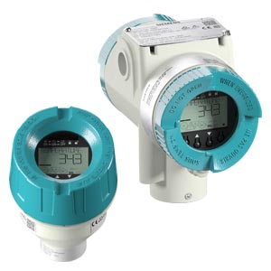
SITRANS TF420 in dual chamber enclosure

SITRANS TF420 in single chamber enclosure

  • 2‑wire temperature transmitter with HART communication interface
  • Universal input for virtually any type of temperature sensor
  • Connection of two independent input circuits for redundant operation (high input availability)
  • Input drift detection
  • Can be configured via PC, HART 7 or optional local operation

Benefits

  • Universally applicable as a temperature transmitter with galvanic isolation for:
    • Resistance thermometer (2-wire, 3-wire, 4-wire connection)
    • Thermocouples
    • Linear resistances, potentiometer and DC voltage sources
  • Local operation of the temperature transmitter via display (single chamber enclosure) or control keys accessible from outside (dual chamber enclosure)
  • Rugged single or dual chamber enclosure made of die-cast aluminum or stainless steel 316/316L
  • Electronic compartment isolated (watertight) from terminal compartment in dual chamber enclosure
  • Degree of protection IP66/68 (1.5 m/2 h)
  • Electromagnetic compatibility according to EN 61326 and NE21
  • Test terminals for direct read-out of the output signal without breaking the current loop
  • Remote installation option:
    • Measuring point is difficult to access
    • Measuring point is subjected to high temperatures
    • Measuring point is subjected to vibration through plant
    • Long neck pipes and thermowells must be avoided
  • Temperature transmitters of the "intrinsically safe protection type, increased safety for zone 2, flameproof and dust-protected" type of protection can be installed in hazardous areas. The transmitter meets the requirements of the EU Directive 2014/34/EU (ATEX), the FM and CSA regulations as well as other national approvals, e.g. EACEx, NEPSI, KCs, Inmetro.
  • SIL2/3 (with order note C20) according to IEC 61508 and Electrical Equipment For Furnaces And Ancillary Equipment (EN 50156-2)

Application

SITRANS TF420 with its two sensor inputs can be used everywhere where temperatures need to be measured without interruption under particularly adverse conditions and where a convenient local display is ideal. Which is why users from all industries have opted for this field device. The rugged enclosure protects the electronics. The stainless steel model is almost completely resistant to sea water and other aggressive substances. The inner workings offer high measuring accuracy, universal input and a wide range of diagnostic options.


Function

Configuration

The communication capability over the HART protocol V 7 permits parameterization using a PC or HART communicator (hand-held communicator). The SIMATIC PDM makes it easy.

The optional local operation on the device gives you the possibility to configure the device's most important functions very quickly.

Principle of operation

SITRANS TF420 as temperature transmitter

Two sensor signals, whether resistance thermometers (RTD), thermocouples (TC), Ω or mV signals, are amplified and linearized. Input and output side are galvanically isolated. An internal cold junction is integrated for measurements with thermocouples.

The device outputs a temperature-linear direct current from 4 to 20 mA. As well as the analog transmission of measured values from 4 to 20 mA, the HART version also supports digital communication for online diagnostics, measured value transmission, and configuration.

SITRANS TF420 automatically detects when a sensor should be interrupted or is indicating a short-circuit. If the back-up functionality has been selected in the primary value display, the SITRANS TF420 automatically switches to the 2nd input without interrupting the measured value; e.g. primary value input 1 with input 2 as backup. The practical test terminals allow direct measurement of 4 to 20 mA signals over an ammeter without interrupting the output current loop.

Function block diagram SITRANS TF420 with integrated SITRANS TH420

Technical specifications

SITRANS TF420 (HART, universal)

General


Supply voltage1) 2)


  • Without explosion protection (non-Ex)

10.5 ... 48 V DC

  • With explosion protection (Ex i)

10.5 ... 30 V DC

Additional minimum supply voltage when using test terminals

0.8 V

Maximum power loss

≤ 850 mW

Minimum load resistance at supply voltage > 37 V

(Vsupply - 37 V)/23 mA

Insulation voltage, test/operation


  • Without explosion protection (non-Ex)

2.5 kV AC/55 V AC

  • With explosion protection (Ex i)

2.5 kV AC/42 V AC

Polarity protection

All inputs and outputs

Write protection

Wire jumper (transmitter), switch (on display) or software

Warm-up time

< 5 min

Starting time

< 2.75 s

Programming

HART

Signal-to-noise ratio

> 60 dB

Long-term stability

Better than:

  • ± 0.05% of measuring span/year
  • ± 0.18% of measuring span/5 years

Response time

4 ... 20 mA: ≤ 55 ms

HART: ≤ 75 ms (typically 70 ms)

Programmable damping

0 ... 60 s

Signal dynamic


  • Input

24 bit

  • Output

18 bit

Influence of change in supply voltage

< 0.005% of measuring span/V DC

Input


Resistance thermometer (RTD)


Input type


  • Pt10 ... 10000
  • IEC 60751
  • JIS C 1604‑8
  • GOST 6651_2009
  • Callendar-Van Dusen
  • Ni10 ... 10000
  • DIN 43760-1987
  • GOST 6651-2009/OIML R84:2003
  • Cu5 ... 1000
  • Edison Copper Winding No. 15
  • GOST 6651‑2009/OIML R84:2003

Connection type

2-wire, 3-wire or 4-wire

Wire resistance per wire

Max. 50 Ω

Input current

< 0.15 mA

Effect of the wire resistance (with 3-wire and 4-wire connections)

< 0.002 Ω/Ω

Cable, wire-wire capacity


  • Pt1000, Pt10000 (IEC 60751 and JIS C 1604‑8)

Max. 30 nF

  • All other input types

Max. 50 nF

Fault detection, programmable

None, short-circuited, defective, short-circuited or defective

Note

When the low limit for the configured input type is below the constant detection limit for short-circuited inputs, the detection of short circuits is disabled regardless of the configuration of the fault detection.

Detection limit for short-circuited input

15 Ω

Fault detection time (RTD)

≤ 75 ms (typically 70 ms)

Fault detection time (for 3-wire and 4-wire)

≤ 2 000 ms

Thermocouples (TC)


Input type


  • B

IEC 60584‑1

  • E

IEC 60584‑1

  • J

IEC 60584‑1

  • K

IEC 60584‑1

  • L

DIN 43710

  • Lr

GOST 3044‑84

  • N

IEC 60584‑1

  • R

IEC 60584‑1

  • S

IEC 60584‑1

  • T

IEC 60584‑1

  • U

DIN 43710

  • W3

ASTM E988‑96

  • W5

ASTM E988‑96

  • LR

GOST 3044‑84

Cold Junction Compensation (CJC)

Constant, internal or external over Pt100 or Ni100 RTD

  • Temperature range internal CJC

-50 ... +100 °C (-58 ... +212 °F)

  • Connection external CJC

2-wire or 3-wire

  • External CJC, wire resistance per wire (for 3-wire and 4-wire connections)

50 Ω

  • Effect of the wire resistance (with 3-wire and 4-wire connections)

< 0.002 Ω/Ω

  • Input current external CJC

< 0.15 mA

  • Temperature range external CJC

‑50 ... +135 °C (‑58 ... +275 °F)

  • Cable, wire-wire capacity

Max. 50 nF

  • Total wire resistance

Max. 10 kΩ

  • Fault detection, programmable

None, short-circuited, defective, short-circuited or defective

Note

The short-circuited fault detection only applies to the CJC input.

  • Fault detection time (TC)

≤ 75 ms (typically 70 ms)

  • Fault detection time, external CJC (for 3-wire and 4-wire)

≤ 2 000 ms

Linear resistance


Input range

10 Ω ... 100 kΩ

Minimum measuring span

25 Ω

Connection type

2-wire, 3-wire or 4-wire

Wire resistance per wire

Max. 50 Ω

Input current

< 0.15 mA

Effect of the wire resistance (with 3-wire and 4-wire connections)

< 0.002 Ω/Ω

Cable, wire-wire capacity


  • R > 400 Ω

Max. 30 nF

  • R ≤ 400 Ω

Max. 50 nF

Fault detection, programmable

None, defective

Potentiometers


Input range

0 ... 100 kΩ

Minimum measuring span

25 Ω

Connection type

2-wire, 3-wire or 4-wire

Wire resistance per wire

Max. 50 Ω

Input current

< 0.15 mA

Effect of the wire resistance (with 4-wire and 5-wire connections)

< 0.002 Ω/Ω

Cable, wire-wire capacity


  • R > 400 Ω

Max. 30 nF

  • R ≤ 400 Ω

Max. 50 nF

Fault detection, programmable

None, short-circuited, defective, short-circuited or defective

Note

When the configured potentiometer size is below the constant detection limit for short-circuited inputs, the detection of short circuits is disabled regardless of the configuration of the fault detection.

Detection limit for short-circuited input

15 Ω

Fault detection time, wiper arm (no short-circuit detection)

≤ 75 ms (typically 70 ms)

Fault detection time, element

≤ 2 000 ms

Fault detection time (for 4-wire and 5-wire)

≤ 2 000 ms

Supply voltage


Measuring range


  • Unipolar

‑100 ... 1700 mV

  • Bipolar

‑800 ... +800 mV

Minimum measuring span

2.5 mV

Input resistance

10 MΩ

Cable, wire-wire capacity


  • Input range: ‑100 ... 1700 mV

Max. 30 nF

  • Input range: ‑20 ... 100 mV

Max. 50 nF

Fault detection, programmable

None, defective

Fault detection time

≤ 75 ms (typically 70 ms)

Output and HART communication


Normal range, programmable

3.8 ... 20.5 mA/20.5 ... 3.8 mA

Extended range (output limits), programmable

3.5 ... 23 mA/23 ... 3.5 mA

Programmable input/output limits


  • Fault current

Enable/disable

  • Fault current setting

3.5 ... 23 mA

Update time

10 ms

Load (with current output)

≤ (VSupply - 10.5)/0.023 Ω

Load stability

< 0.01% of measuring span/100 Ω (measuring span = currently selected range)

Input fault detection, programmable (detection of input short-circuits is ignored with TC and voltage inputs)

3.5 ... 23 mA

NAMUR NE43 Upscale

> 21 mA

NAMUR NE43 Downscale

< 3.6 mA

HART protocol versions

HART 7

Measuring accuracy


Input accuracy

See "Input accuracy" table

Output accuracy

See "Output accuracy" table

Operating conditions


Ambient temperature


  • Without local operation in single chamber enclosure

‑50 ... +85 °C (‑58 ... +185 °F)

  • With local operation

‑40 ... +85 °C (‑40 ... +185 °F)

  • For transmitters with functional safety

‑40 ... +80 °C (‑40 ... +176 °F)

Storage temperature

‑50 ... +85 °C (‑58 ... +185 °F)

Reference temperature for sensor calibration

24 °C ±1.0 °C (75.2 °F ±1.8 °F)

Relative humidity

< 99% (no condensation)

Degree of protection


  • Temperature transmitter enclosure

IP66/IP68

  • Terminals

IP00

Structural design


Weight


  • Single chamber enclosure
  • Aluminum: 0.85 kg (1.87 lbs)
  • Stainless steel: 1.69 kg (3.73 lbs)
  • Dual chamber enclosure
  • Aluminum: 1.3 kg (2.87 lbs)
  • Stainless steel: 3.3 kg (7.28 lbs)

Maximum core cross-section


  • Single chamber enclosure

1.5 mm² (AWG 16)

  • Dual chamber enclosure

2.5 mm² (AWG 14)

Tightening torque for clamping screws

0.5 ... 0.6 Nm

Vibrations

IEC 60068‑2‑6

  • 2 ... 25 Hz

± 1.6 mm (0.07 inches)

  • 25 ... 100 Hz

± 4 g

Certificates and approvals


Explosion protection ATEX/IECEx and others


Certificates3)

  • IECEx DEK 19.0069X
  • IECEx DEK 19.0070X
  • DEKRA 19ATEX0106 X (Category 1)
  • DEKRA 19ATEX0108X (Category 2)
  • DEKRA 19ATEX0107X (Category 3)
  • A5E50642461A‑2021X (Category 3)

"Intrinsic safety ia/ib" type of protection

For use in Zone 0, 1, 2, 21

  • ATEX
  • II 1 G Ex ia IIC T6 ... T4 Ga
  • II 2 (1) G Ex ib [ia Ga] IIC T6 ... T4 Gb
  • II 2 (1) D Ex ib [ia Da] IIIC T100 °C Db
  • IECEx and others
  • Ex ia IIC T6 ... T4 Ga
  • Ex ib [ia Ga] IIC T6 ... T4 Gb
  • Ex ib [ia Da] IIIC T 100 °C Db

"Intrinsic safety ic" type of protection

For use in Zone 2, 22

  • ATEX
  • II 3 G Ex ic IIC T6…T4 Gc
  • II 3 D Ex ic IIIC T100 °C Dc
  • IECEx and others
  • Ex ic IIC T6 ... T4 Gc
  • Ex ic IIIC T100 °C Dc

"Increased safety ec" type of protection

For use in Zone 2

  • ATEX

II 3 G Ex ec IIC T6…T4 Gc

  • IECEx and others

Ex ec IIC T6 ... T4 Gc

  • "Flameproof enclosure db" type of protection

For use in Zone 1

  • ATEX

II 2 G Ex db IIC T6…T4 Gb

  • IECEx and others

Ex db IIC T6 ... T4 Gb

  • "Protection by enclosure tb/tc" type of protection

For use in Zone 21, 22

  • ATEX
  • II 2 D Ex tb IIC T100 °C Db
  • II 3 D Ex tc IIIC T100 °C Dc
  • IECEx and others
  • Ex tb IIC T100 °C Db
  • Ex tc IIIC T100 °C Dc


1) Note that the minimum supply voltage must correspond to the value measured at the terminals of the SITRANS TF420. All external voltage drops must be taken into account.

2) Protect the device from overvoltage with the help of a suitable power supply or suitable overvoltage protection equipment.

3) Additional available certificates are listed on the internet at http://www.siemens.com/processinstrumentation/certificates

Measuring ranges/Minimum measuring span

RTD

Input type

Standard

Measuring range in °C (°F)

α0 in °C-1 (°F-1)

Minimum measuring span in °C (°F)

Pt10 ... 10000

IEC 60751

‑200 ... +850 (‑328 ... +1 562)

0.003851 (0.002139)

10 (50)

JIS C 1604‑8

‑200 ... +649 (‑328 ... +1 200)

0.003916 (0.002176)

10 (50)

GOST 6651_2009

‑200 ... +850 (‑328 ... +1 562)

0.003910 (0.002172)

10 (50)

Callendar-Van Dusen

‑200 ... +850 (‑328 ... +1 562)

-

10 (50)

Ni10 ... 10000

DIN 43760-1987

‑60 ... +250 (‑76 ... +482)

0.006180 (0.003433)

10 (50)

GOST 6651-2009/OIML R84:2003

‑60 ... +180 (‑76 ... +356)

0.006170 (0.003428)

10 (50)

Cu5 ... 1000

Edison Copper Winding No. 15

‑200 ... +260 (‑328 ... +500)

0.004270 (0.002372)

100 (212)

GOST 6651‑2009/OIML R84:2003

‑180 ... +200 (‑292 ... +392)

0.004280 (0.002378)

100 (212)

GOST 6651‑94

‑50 ... +200 (‑58 ... +392)

0.004260 (0.002367)

100 (212)


TC

Input type

Standard

Measuring range in °C (°F)

Minimum measuring span in °C (°F)

B

IEC 60584‑1

0 (85) ... 1 820 (32 (185) ... 3 308)

100 (212)

E

IEC 60584‑1

‑200 ... +1 000 (‑392 ... +1 832)

50 (122)

J

IEC 60584‑1

‑100 ... +1 200 (‑212 ... +2 192)

50 (122)

K

IEC 60584‑1

‑180 ... +1 372 (‑356 ... +2 502)

50 (122)

L

DIN 43710

‑200 ... +900 (‑392 ... +1 652)

50 (122)

Lr

GOST 3044‑84

‑200 ... +800 (‑392 ... +1 472)

50 (122)

N

IEC 60584‑1

‑180 ... +1 300 (‑356 ... +2 372)

50 (122)

R

IEC 60584‑1

‑50 ... +1 760 (‑122 ... +3 200)

100 (212)

S

IEC 60584‑1

‑50 ... +1 760 (‑122 ... +3 200)

100 (212)

T

IEC 60584‑1

‑200 ... +400 (‑392 ... +752)

50 (122)

U

DIN 43710

‑200 ... +600 (‑392 ... +1 112)

50 (122)

W3

ASTM E988‑96

0 ... 2 300 (32 ... 4 172)

100 (212)

W5

ASTM E988‑96

0 ... 2 300 (32 ... 4 172)

100 (212)

LR

GOST 3044‑84

‑200 ... +800 (‑392 ... +1472)

50 (122)


Input accuracy

Basic values

Input type

Basic accuracy

Temperature coefficient1)

RTD


Pt10

≤ ±0.8 °C (1.44 °F)

≤ ±0.020 °C/°C (°F/°F)

Pt20

≤ ±0.4 °C (0.72 °F)

≤ ±0.010 °C/°C (°F/°F)

Pt50

≤ ±0.16 °C (0.288 °F)

≤ ±0.004 °C/°C (°F/°F)

Pt100

≤ ±0.04 °C (0.072 °F)

≤ ±0.002 °C/°C (°F/°F)

Pt200

≤ ±0.08 °C (0.144 °F)

≤ ±0.002 °C/°C (°F/°F)

Pt500

Tmax. < 180 °C (356 °F) = ≤ ±0.08 °C (0.144 °F)

Tmax. > 180 °C (356 °F) = ≤ ±0.16 °C (0.288 °F)

≤ ±0.002 °C/°C (°F/°F)

Pt1000

≤ ±0.08 °C (0.144 °F)

≤ ±0.002 °C/°C (°F/°F)

Pt2000

Tmax. < 300 °C (572 °F) = ≤ ±0.08 °C (0.144 °F)

Tmax. > 300 °C (572 °F) = ≤ ±0.4 °C (0.72 °F)

≤ ±0.002 °C/°C (°F/°F)

Pt10000

≤ ±0.16 °C (0.288 °F)

≤ ±0.002 °C/°C (°F/°F)

Pt x

Largest tolerance of neighboring points

Largest temperature coefficient of neighboring points

Ni10

≤ ±1.6 °C (2.88 °F)

≤ ±0.020 °C/°C (°F/°F)

Ni20

≤ ±0.8 °C (1.44 °F)

≤ ±0.010 °C/°C (°F/°F)

Ni50

≤ ±0.32 °C (0.576 °F)

≤ ±0.004 °C/°C (°F/°F)

Ni100

≤ ±0.16 °C (0.288 °F)

≤ ±0.002 °C/°C (°F/°F)

Ni120

≤ ±0.16 °C (0.288 °F)

≤ ±0.002 °C/°C (°F/°F)

Ni200

≤ ±0.16 °C (0.288 °F)

≤ ±0.002 °C/°C (°F/°F)

Ni500

≤ ±0.16 °C (0.288 °F)

≤ ±0.002 °C/°C (°F/°F)

Ni1000

≤ ±0.16 °C (0.288 °F)

≤ ±0.002 °C/°C (°F/°F)

Ni2000

≤ ±0.16 °C (0.288 °F)

≤ ±0.002 °C/°C (°F/°F)

Ni10000

≤ ±0.32 °C (0.576 °F)

≤ ±0.002 °C/°C (°F/°F)

Ni x

Largest tolerance of neighboring points

Largest temperature coefficient of neighboring points

Cu5

≤ ±1.6 °C (2.88 °F)

≤ ±0.040 °C/°C (°F/°F)

Cu10

≤ ±0.8 °C (1.44 °F)

≤ ±0.020 °C/°C (°F/°F)

Cu20

≤ ±0.4 °C (0.72 °F)

≤ ±0.010 °C/°C (°F/°F)

Cu50

≤ ±0.16 °C (0.288 °F)

≤ ±0.004 °C/°C (°F/°F)

Cu100

≤ ±0.08 °C (0.144 °F)

≤ ±0.002 °C/°C (°F/°F)

Cu200

≤ ±0.08 °C (0.144 °F)

≤ ±0.002 °C/°C (°F/°F)

Cu500

≤ ±0.16 °C (0.288 °F)

≤ ±0.002 °C/°C (°F/°F)

Cu1000

≤ ±0.08 °C (0.144 °F)

≤ ±0.002 °C/°C (°F/°F)

Cu x

Largest tolerance of neighboring points

Largest temperature coefficient of neighboring points

Linear resistance


0 ... 400 Ω

≤ ±40 mΩ

≤ ±2 mΩ/°C (1.11 mΩ/°F)

0 ... 100 kΩ

≤ ±4 Ω

≤ ±0.2 Ω/°C (0.11 Ω/°F)

Potentiometers


0 ... 100%

< 0.05%

< ± 0.005%

Supply voltage


mV: -20 ... 100 mV

≤ ±5 μV

≤ ±0.2 μV/°C (0.11 μV/°F)

mV: -100 ... 1700 mV

≤ ±0.1 mV

≤ ±36 μV/°C (20 μV/°F)

mV: ± 800 mV

≤ ±0.1 mV

≤ ±32 μV/°C (17.8 μV/°F)

TC


E

≤ ±0.2 °C (0.36 °F)

≤ ±0.025 °C/°C (°F/°F)

J

≤ ±0.25 °C (0.45 °F)

≤ ±0.025 °C/°C (°F/°F)

K

≤ ±0.25 °C (0.45 °F)

≤ ±0.025 °C/°C (°F/°F)

L

≤ ±0.35 °C (0.63 °F)

≤ ±0.025 °C/°C (°F/°F)

N

≤ ±0.4 °C (0.72 °F)

≤ ±0.025 °C/°C (°F/°F)

T

≤ ±0.25 °C (0.45 °F)

≤ ±0.025 °C/°C (°F/°F)

U

< 0 °C (32 °F) ≤ ±0.8 °C (1.44 °F)

≥ 0 °C (32 °F) ≤ ±0.4 °C (0.72 °F)

≤ ±0.025 °C/°C (°F/°F)

Lr

≤ ±0.2 °C (0.36 °F)

≤ ±0.1 °C/°C (°F/°F)

R

< 200 °C (392 °F) ≤ ±0.5 °C (0.9 °F)

≥ 200 °C (392 °F) ≤ ±1 °C (1.8 °F)

≤ ±0.1 °C/°C (°F/°F)

S

< 200 °C (392 °F) ≤ ±0.5 °C (0.9 °F)

≥ 200 °C (392 °F) ≤ ±1 °C (1.8 °F)

≤ ±0.1 °C/°C (°F/°F)

W3

≤ ±0.6 °C (1.08 °F)

≤ ±0.1 °C/°C (°F/°F)

W5

≤ ±0.4 °C (0.72 °F)

≤ ±0.1 °C/°C (°F/°F)

B2)

≤ ±1 °C (1.8 °F)

≤ ±0.1 °C/°C (°F/°F)

B3)

≤ ±3 °C (5.4 °F)

≤ ±0.1 °C/°C (°F/°F)

B4)

≤ ±8 °C (14.4 °F)

≤ ±0.8 °C/°C (°F/°F)

B5)

Not specified

Not specified

CJC (internal)

< ±0.5 °C (0.9 °F)

Included in basic accuracy

CJC (external)

≤ ±0.08 °C (0.144 °F)

≤ ±0.002 °C/°C (°F/°F)


1) Temperature coefficients correspond to the specified values or 0.002% of the input span, depending on which value is greater.

2) Accuracy of the specification range > 400 °C (752 °F)

3) Accuracy of the specification range > 160 °C (320 °F) < 400 °C (752 °F)

4) Accuracy of the specification range > 85 °C (185 °F) < 160 °C (320 °F)

5) Accuracy of the specification range < 85 °C (185 °F)

Output accuracy

Output type

Basic accuracy

Temperature coefficient

Average value measurement

Average of accuracy of input 1 and input 2

Average of temperature coefficient of input 1 and input 2

Differential measurement

Sum of accuracy of input 1 and input 2

Sum of temperature coefficient of input 1 and input 2

Analog output

≤ ±1.6 μA (0.01% of the full output span)

≤ ±0.48 μA/K (≤ ±0.003% of the full output span/K)

Dimensional drawings

SITRANS TF420, single chamber enclosure, dimensions in mm (inch)

SITRANS TF420, dual chamber enclosure, dimensions in mm (inch)


Circuit diagrams

Connections

Input connection

SITRANS TF420 in single chamber enclosure (7NG044*), input connection assignment

SITRANS TF420 in dual chamber enclosure (7NG045*), input connection assignment

Output connection

SITRANS TF420 in single chamber enclosure (7NG044*), output connection assignment


1 đánh giá SITRANS TF420 (HART, UNIVERSAL) Overview

5

Chọn đánh giá của bạn
Zalo Facebook

Liên Hệ

Công ty CP Cơ điện tử Minh Khang - Đại diện ủy quyền của hãng SIEMENS tại Việt Nam - Nhà tích hợp hệ thống tự động hóa toàn diện